Review Tdr2 Build Pics

Discussion in 'Henseleit' started by ChopsyWA, May 3, 2016.

By ChopsyWA on May 3, 2016 at 3:51 PM
  1. ChopsyWA

    ChopsyWA Well-Known Member

    Joined:
    May 31, 2014
    Messages:
    365
    Likes Received:
    306
    The following thread will show the build progress of my new Henseleit TDR2.
    This will be a little slow going, but I hope to progress thru it over the coming week before I head back north for work.

    It comes packaged in two parcels, as a way to avoid added tax cost due to high value. As I did not purchase any electronics with it, I just got a box with everything and the blade caddy in a separate envelope (700euro blade caddy :p ).

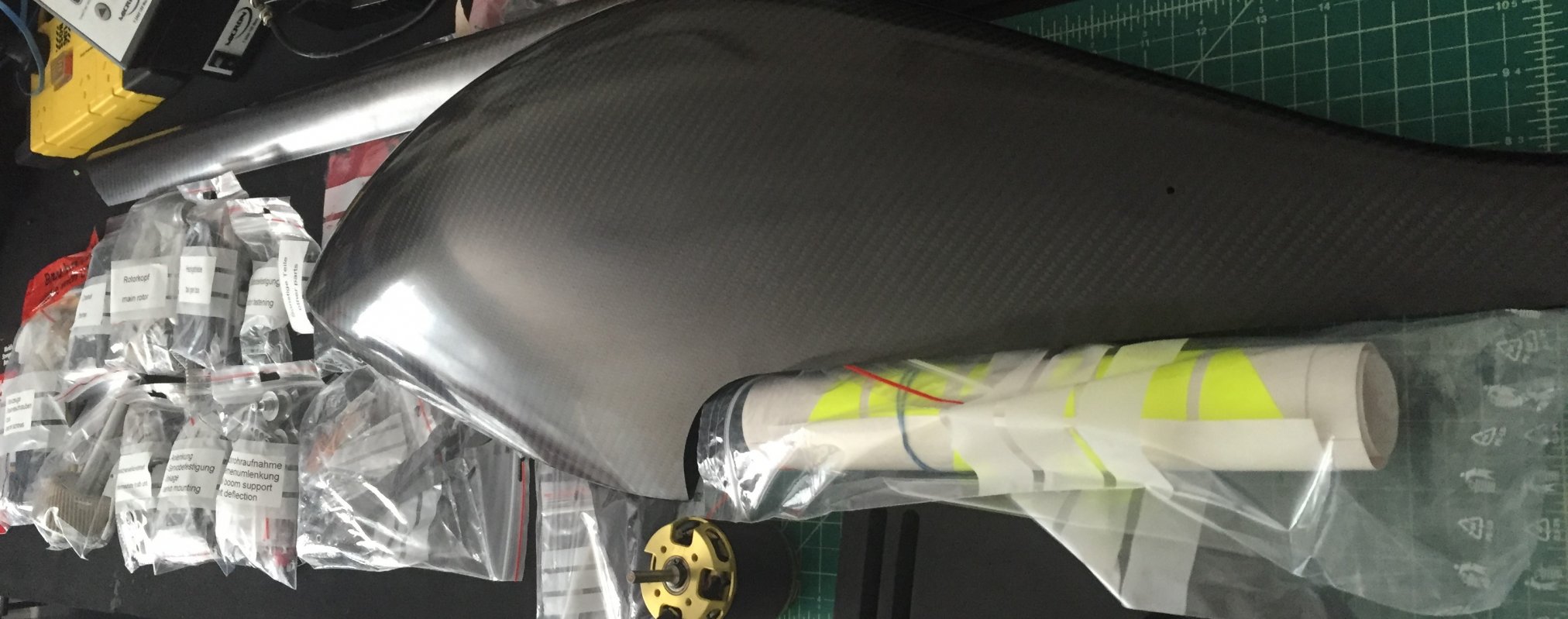
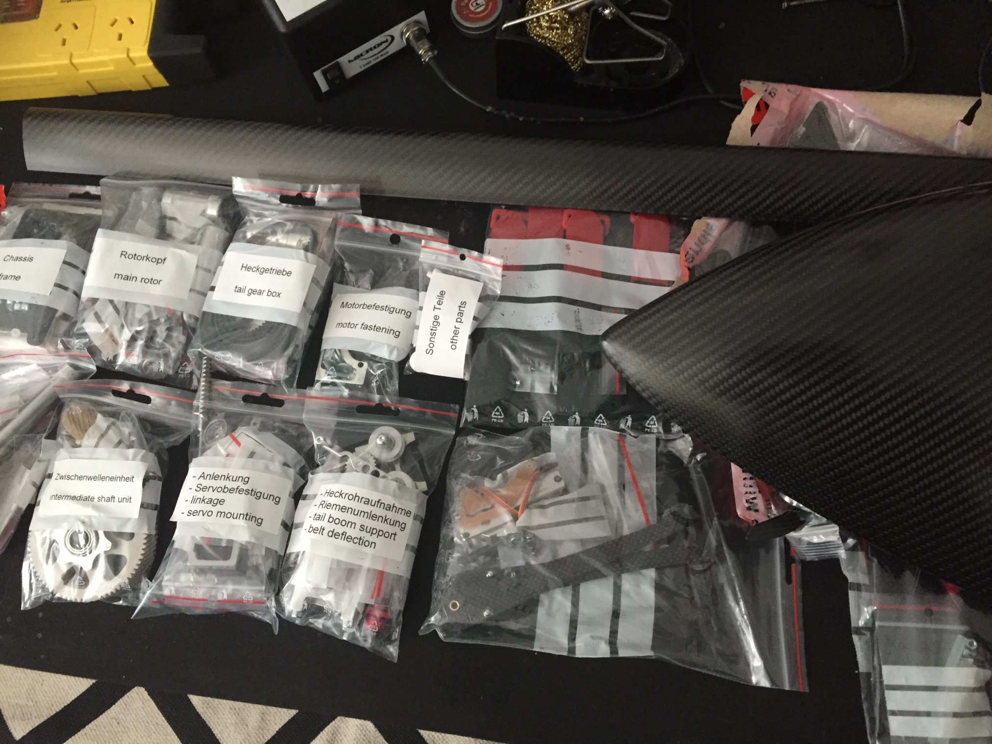
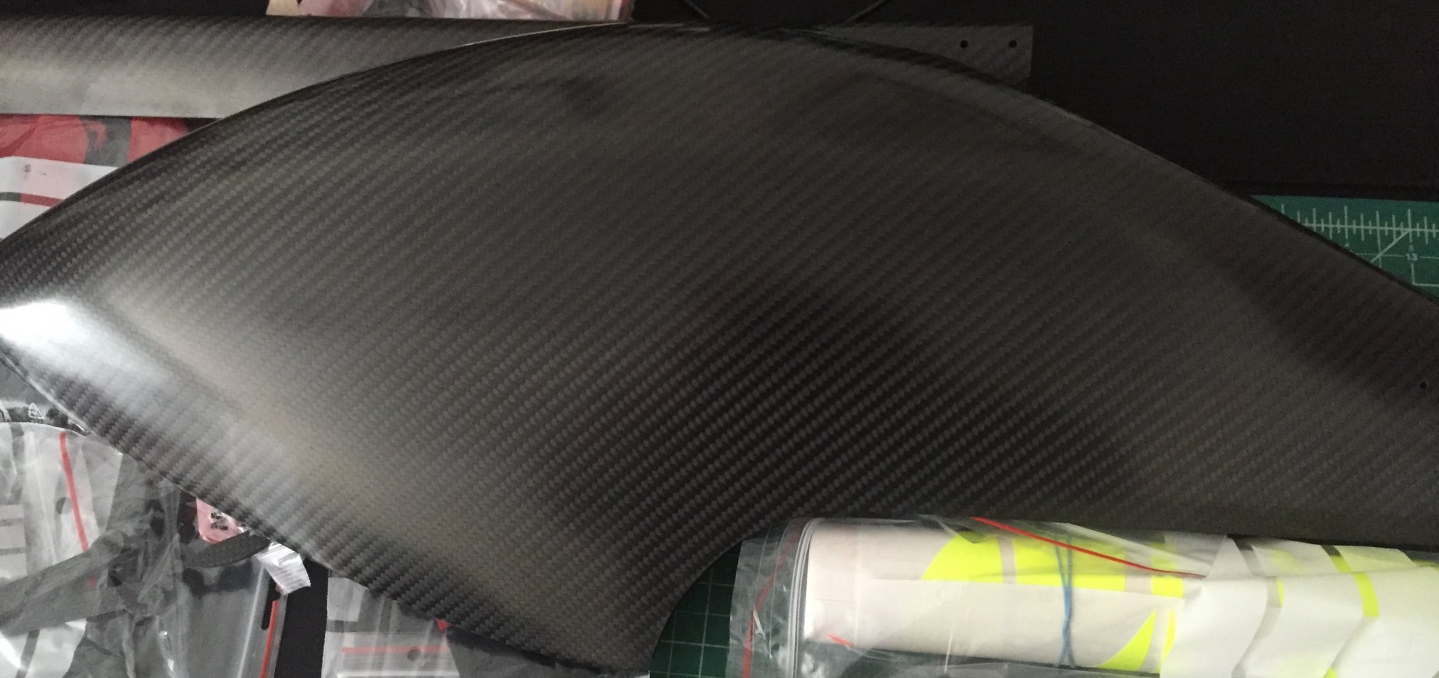
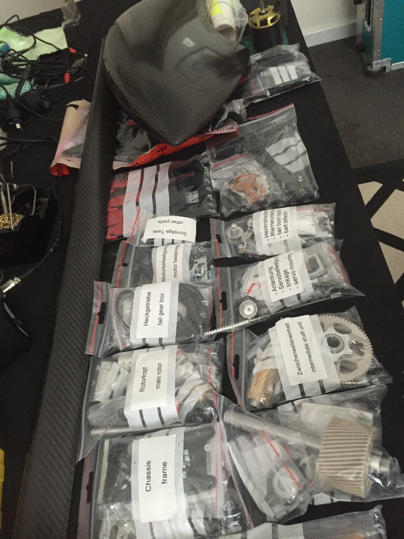
    The canopy is sensational, so glad I paid a little extra for the CF canopy instead of going poor with the GF version. And the CF boom is out of this world! All the mechanics are in labeled section bags, matching up with the 108 page manual. Its recommended to not open up and bag until working on that section from the manual, as this being a high-parts count one would hate to loose track! :)

    https://www.dropbox.com/s/461e07uxuam3tbs/TDR-II manual.pdf?dl=0

    IMG_6703.JPG

    IMG_6704.JPG

    IMG_6705.JPG

    IMG_6706.JPG


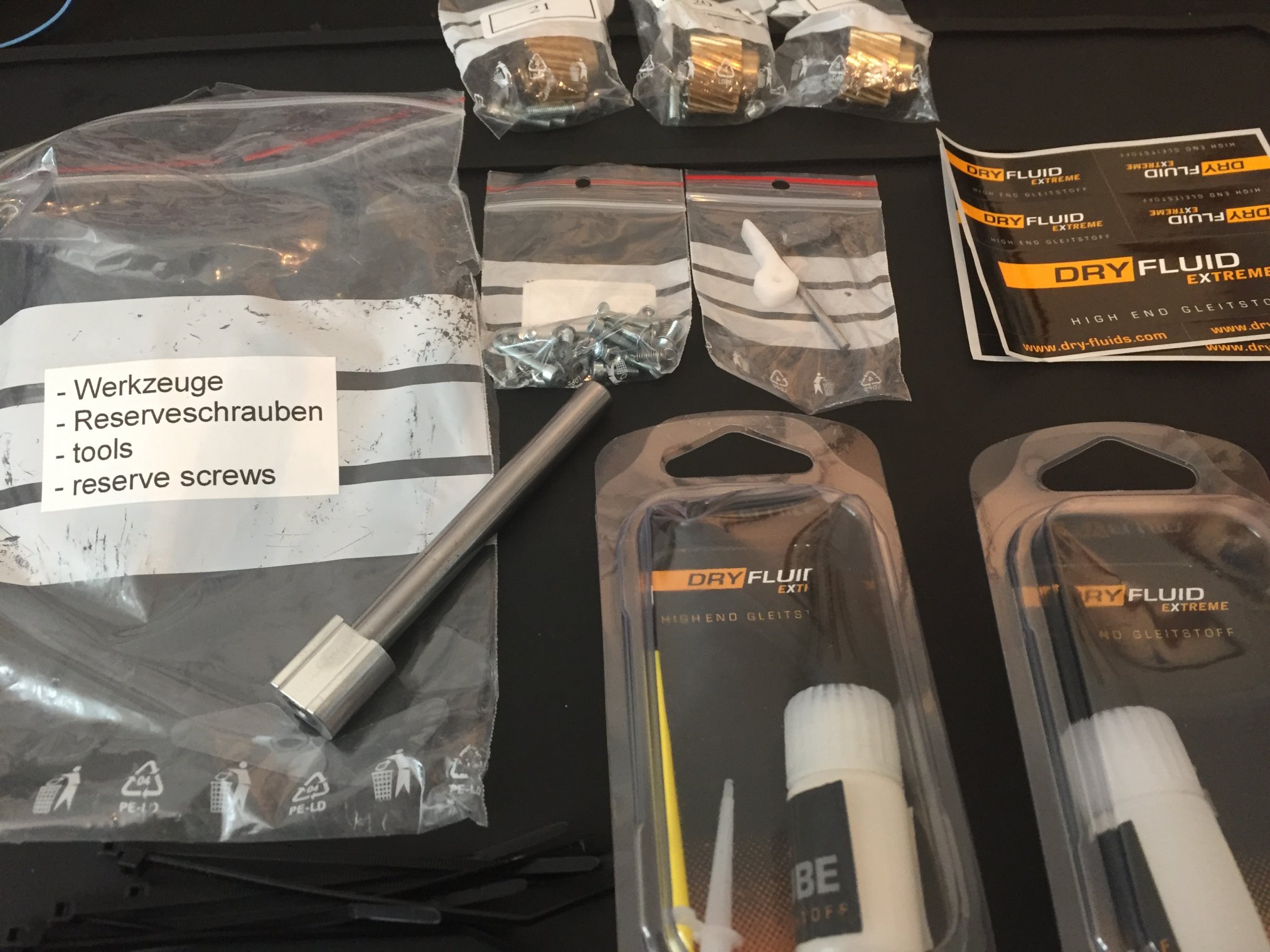
    The kit comes with a bag of extra bolts, tools and Dry-Fluid bottles. And let me say that at the rate this kit is impressing me - I'm going to be using all the DryFluid lube on myself!!! :eek::D:p:p:cool:
    IMG_6710.JPG
     
    Last edited: May 4, 2016
    • Like Like x 2
    • Funny Funny x 1
    • List

Comments

Discussion in 'Henseleit' started by ChopsyWA, May 3, 2016.

  • Tags:
    1. ChopsyWA

      ChopsyWA Well-Known Member

      Joined:
      May 31, 2014
      Messages:
      365
      Likes Received:
      306
      First step, building the main rotor head!

      IMG_6707.JPG

      This shows the central head dampening adjustment bush. LH & RH threads allow the central driver to be rotated to send out the two nuts thus squeezing the orings together and making for tighter dampening. No more disassembling and changing out different duro orings!
      IMG_6711.JPG

      IMG_6712.JPG

      IMG_6713.JPG

      IMG_6714.JPG

      IMG_6715.JPG

      IMG_6716.JPG

      IMG_6717.JPG

      IMG_6719.JPG

      Fitted to the blade grips are top-hat bushes to protect the aluminium grip from the hard bolt. This bush also protrudes 0.7mm into the grip area to locate the blade-grip-washer, so no more plastic blade grip washers slipping about when inserting the blades :D
      IMG_6718.JPG
       
      Last edited: May 3, 2016
    2. ChopsyWA

      ChopsyWA Well-Known Member

      Joined:
      May 31, 2014
      Messages:
      365
      Likes Received:
      306
      Next is the Main Shaft/Gear checking over. Already pre-assembled, just check over. All pre-assembled parts have been done up with loctite at torque wrench settings from Henseleit.

      The size of the peak main gear on the Ø15mm main shaft is impressive.

      IMG_6721.JPG

      IMG_6723.JPG

      Next up, the intermediate shaft section. Once again just a check over the pre-assembled parts. Damn this stuff has been well made ;)
      IMG_6724.JPG


      Next up, fitting the main and intermediate shafts to the chassis plates.
      IMG_6726.JPG

      Managed to save a bit of the DryFluid Gear Lube for the heli... :eek:
      IMG_6727.JPG

      IMG_6728.JPG


      Next a bit of CF sanding, got to radius one edge where the motor wires will pass over.
      IMG_6729.JPG


      Very tidy little package :cool:

      IMG_6733.JPG

      IMG_6734.JPG

      IMG_6735.JPG
       
      Last edited: May 3, 2016
      • Like Like x 2
      • Crash Immunity Crash Immunity x 1
      • List
    3. ChopsyWA

      ChopsyWA Well-Known Member

      Joined:
      May 31, 2014
      Messages:
      365
      Likes Received:
      306
      Next bolting on the skid mount and elevator rack bearing supports.
      IMG_6736.JPG

      IMG_6737.JPG


      Now moving onto the Kosmik mount. This heli was designed on using a Kosmik 200 Cool, but I'm going to try a standard with fan (got it lying around). The Kosmik bolts to the CF plate with nylon bolts.
      IMG_6738.JPG

      IMG_6740.JPG


      Next is time to move onto the tail boom holding section.
      IMG_6743.JPG

      IMG_6745.JPG

      And now to bolt the boom holder to the main gear train section.
      IMG_6746.JPG

      IMG_6747.JPG


      Next is time for the skids. Will be mounting the fixed skids now for building and the first few days out until the heli is dialed in, then will install the retractable skids once happy with the way it fly's.
      IMG_6748.JPG

      IMG_6750.JPG

      IMG_6751.JPG


      Now for the tail servo mounts and tail control canter-leaver.
      IMG_6752.JPG

      IMG_6754.JPG
       
      Last edited: May 4, 2016
    4. ChopsyWA

      ChopsyWA Well-Known Member

      Joined:
      May 31, 2014
      Messages:
      365
      Likes Received:
      306
      Up to the LDS system (Linear Servo Drive).

      No servo horns to be seen...... :D

      IMG_6755.JPG

      Belt driven elevator servo rack arrangement.
      IMG_6759.JPG

      IMG_6760.JPG

      IMG_6761.JPG

      IMG_6762.JPG

      IMG_6763.JPG


      Time for the roll cyclic racks, nice racks indeed! :p
      IMG_6764.JPG

      IMG_6770.JPG

      The bottom guide-rod support is glued to the CF frame. I've never glued anything neatly in my life (even the misses eyelids, always messy when I overshoot the glue... :eek: :rolleyes: ;))...
      IMG_6771.JPG


      Now its time to open my package from RC Japan. Futaba BLS 172sv programmable servos should do the trick :cool:
      IMG_6772.JPG


      Installation of the roll servos.
      IMG_6779.JPG

      IMG_6780.JPG

      IMG_6781.JPG


      Installation of swash and elevator rack. Centering and swash leveling with spacer tool and using Futaba CIU2 programmer.
      [​IMG]

      [​IMG]

      [​IMG]
       
      Last edited: May 5, 2016
    5. ChopsyWA

      ChopsyWA Well-Known Member

      Joined:
      May 31, 2014
      Messages:
      365
      Likes Received:
      306
      Tail boom and tail rotor time. First just glue in the threaded rod into the tail control tube.

      Then apply the text decals to the boom. Applying decals is always shiz for me, not the steadiest hands and I can't ever get them aligned perfect.

      [​IMG]


      Then the decals on the top of the boom. I found if I just use a couple spare kosmiks to hold it upright makes it easier to apply :p:rolleyes::D
      IMG_6786.JPG


      Now its time for assembling the tail case components.
      IMG_6787.JPG

      IMG_6788.JPG

      IMG_6789.JPG

      IMG_6790.JPG

      IMG_6793.JPG

      IMG_6794.JPG

      IMG_6795.JPG

      IMG_6796.JPG

      IMG_6797.JPG

      IMG_6798.JPG

      IMG_6800.JPG
       
      Last edited: May 6, 2016
    6. smakmeharder

      smakmeharder Administrator

      Joined:
      Mar 3, 2014
      Messages:
      4,825
      Likes Received:
      3,096
      Oh wow... very nice. You can really see the quality in the parts...
       
    7. simon

      simon Well-Known Member

      Joined:
      Mar 19, 2014
      Messages:
      3,053
      Likes Received:
      2,403
      Fully sick @ChopsyWA , Love it (and jealous!)
      Simon
       
    8. Stuart

      Stuart Active Member

      Joined:
      May 10, 2014
      Messages:
      405
      Likes Received:
      214
      Wow the gear looks top notch, very impressive

      Stuart
      Citizen #507
       
    9. Finky

      Finky Member

      Joined:
      May 29, 2014
      Messages:
      56
      Likes Received:
      40
      nice work chopsy :)
       
    10. ChopsyWA

      ChopsyWA Well-Known Member

      Joined:
      May 31, 2014
      Messages:
      365
      Likes Received:
      306
      Post above updated, once I've filled post #6 with pics I'll post new so the alerts just happen.

      Will be trying to get it ready to fly by tomorrow evening, so much to do still - but keen to get her airborne!!! :)
       
    11. ChopsyWA

      ChopsyWA Well-Known Member

      Joined:
      May 31, 2014
      Messages:
      365
      Likes Received:
      306
      From this morning, fitting the bicycle tube rubber pieces to the boom, then fitting the boom to the chassis.

      IMG_6801.JPG

      IMG_6802.JPG

      IMG_6803.JPG

      IMG_6804.JPG


      Now time for the main shaft to get some head! :rolleyes::D
      IMG_6805.JPG

      IMG_6806.JPG

      IMG_6807.JPG

      IMG_6808.JPG
       
    12. ChopsyWA

      ChopsyWA Well-Known Member

      Joined:
      May 31, 2014
      Messages:
      365
      Likes Received:
      306
      So onto making up some battery trays. Firstly sand the CF where the joints are so the glue gets a good hold.
      Assemble together then mount onto the front of the heli and hold the tray sides together with lacky bands.
      Then proceed to apply glue to the connection areas, I used Loctite 401 CA glue. Let set on the main frame for at least half-hour before removing from frame.
      IMG_6809.JPG


      Next, this is what ruined my day! Getting a non-pyro motor into this bloody heli!
      It is designed around the pyro 800/850 motors, where the motor shaft circlip is recessed into the stator face, allowing for the design to have the pinion face only 0.8mm away from the stator...
      Unfortunately Scorpion motors have the circlip out from the stator face, and the TDR2 pinions do not have enough spigot inside to allow for recessing the pinion (pinions are grooved internally).
      So I took a new motor shaft into town and turned it along on the lathe to bring the pinion closer to the stator - mine is currently 2mm away but I cannot get closer without re-machining the shaft again and doing away with the circlip...
      It is fitted like this for now, will see how she goes...
      IMG_6812.JPG

      IMG_6814.JPG

      This is the distance before machining the motor shaft - way too far. Sorry I didn't get a pic of after machining & fitting as I was a bit pissed off at the time about this motor dramas...
      IMG_6813.JPG
       
      Last edited: May 7, 2016
    13. Beaver

      Beaver Well-Known Member

      Joined:
      Oct 22, 2014
      Messages:
      2,219
      Likes Received:
      996
      Nice approach to problem solving there!
       
      • Like Like x 2
      • Useful Useful x 1
      • List
    14. hgnimda

      hgnimda Ray - Administrator Staff Member

      Joined:
      Mar 1, 2014
      Messages:
      628
      Likes Received:
      479
      Some very good assembly instructions. Very very informative @ChopsyWA
       
    15. smakmeharder

      smakmeharder Administrator

      Joined:
      Mar 3, 2014
      Messages:
      4,825
      Likes Received:
      3,096
      The tail cage looks to be all one piece. I think you would have a hard time breaking this part and it would be super stable as well. Looking at the images, it would appear that the whole kit just reeks of quality.
       
      • Like Like x 1
      • Agree Agree x 1
      • List
    16. joeclone

      joeclone Active Member

      Joined:
      Feb 3, 2016
      Messages:
      108
      Likes Received:
      61
      Seriously love these kind off build threads, thanks for taking the time to post it up. The kit looks overly complicated but still quality shows, yeah to heli porn.
       
    17. joeclone

      joeclone Active Member

      Joined:
      Feb 3, 2016
      Messages:
      108
      Likes Received:
      61
      Sorry sounding kinda stupid but what does the bicycle tube do on the boom? Looking really out of place in a nice kit.
       
    18. ChopsyWA

      ChopsyWA Well-Known Member

      Joined:
      May 31, 2014
      Messages:
      365
      Likes Received:
      306
      It will go over the canopy back edge where it contacts the boom to hold the canopy tight to boom. The other 4 pieces are put onto the boom so the boom doesn't have to be removed when the first tube wears, as it will eventually break down with use.
      I'll post a pic soon.
       
    19. Beaver

      Beaver Well-Known Member

      Joined:
      Oct 22, 2014
      Messages:
      2,219
      Likes Received:
      996
      Wow! I was just now able to sit down with my laptop and get a really good look at this thing! Transmission looks to be bullet-proof.... rack and pinion swash plate drives.....aerodynamic tail-boom cross section....
      Those Bavarians don't do anything half-a$$ed these days!
      It's like the Mercedes-Benz of the model helicopter world! :eek:
       

Share This Page

test

    About Us

    Just like you, Heligods staff are regular everyday fliers. Join our forum and participate in what will become the worlds greatest rc helicopter forum..

    Credits:

    A big thank you to the following people who helped us put together this site:

    Pope Francis

    Deli Lama

    George Bush

    Gene Simmons (aka Crash)